STM is a distributor for PTE turbochargers. Check in any of the categories above to see what we have to offer!
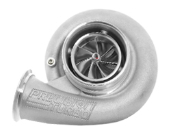
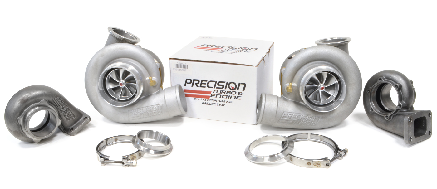
Precision Turbo & Engine is a leader in turbocharger technology with a full line of turbos for street and race, replacement parts, flanges, clamps, gaskets, fittings, and more.
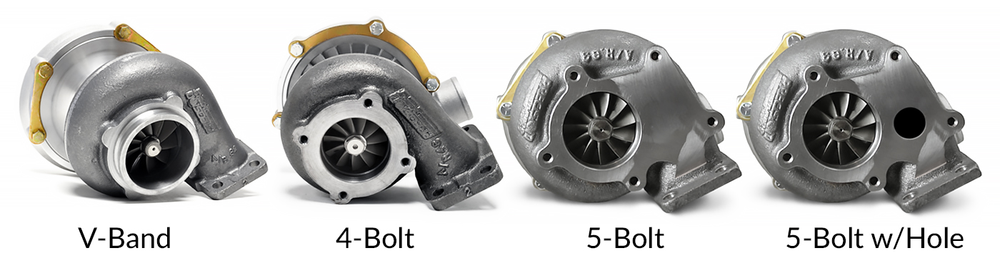
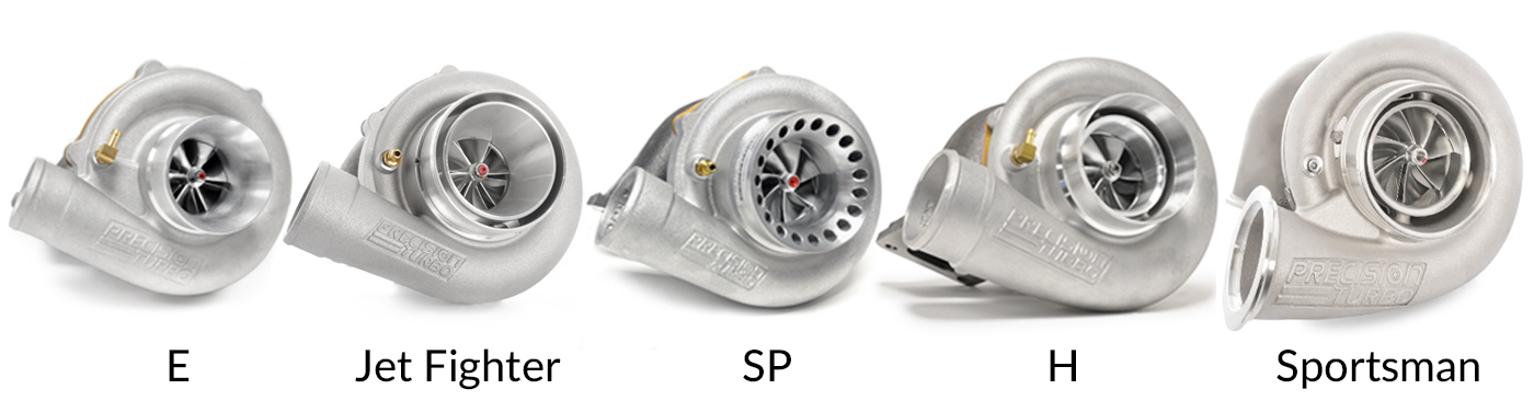
PTE Turbos are available in many different configurations, with various inlet/outlet options and v-band flange sizes. We hope this page can help answer some quick questions and get you familiar with the terminology, but if you need any help, just give us a call. Below you'll find PTE's flange sizes, names and dimensions along with some helpful install tips and YouTube videos.
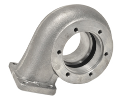
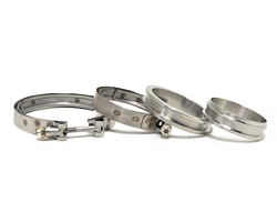
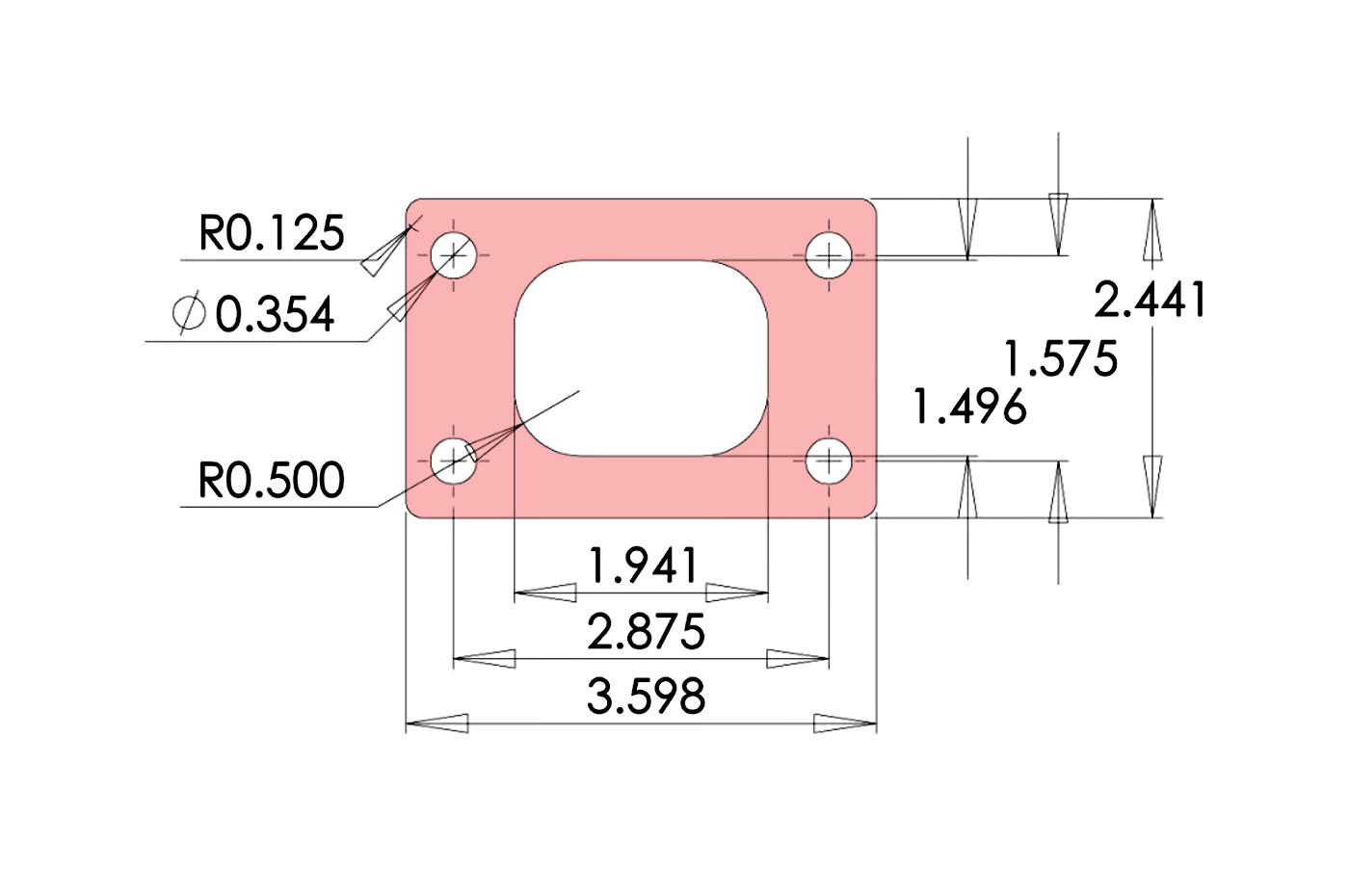
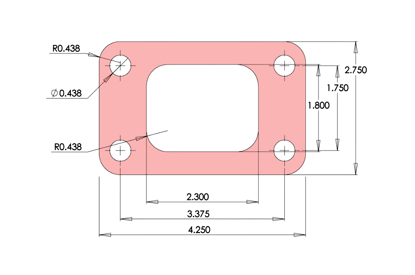
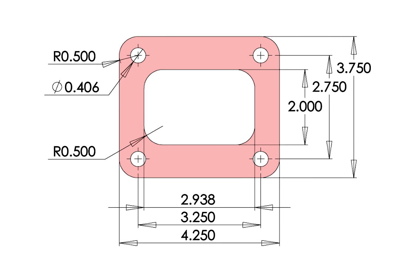
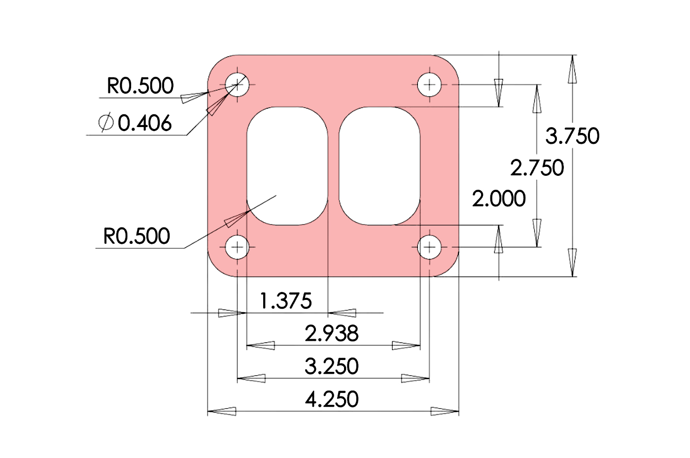
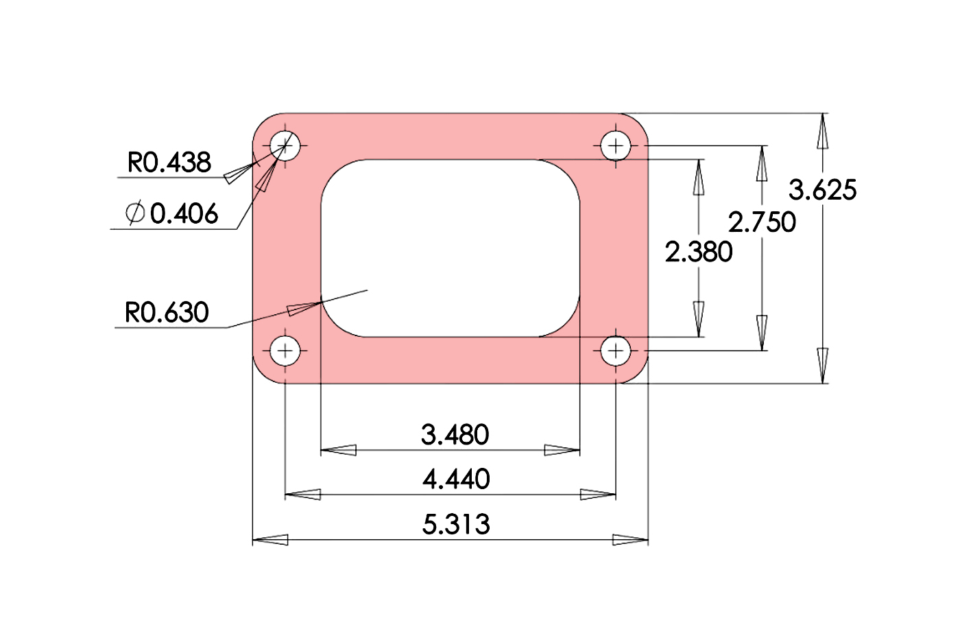
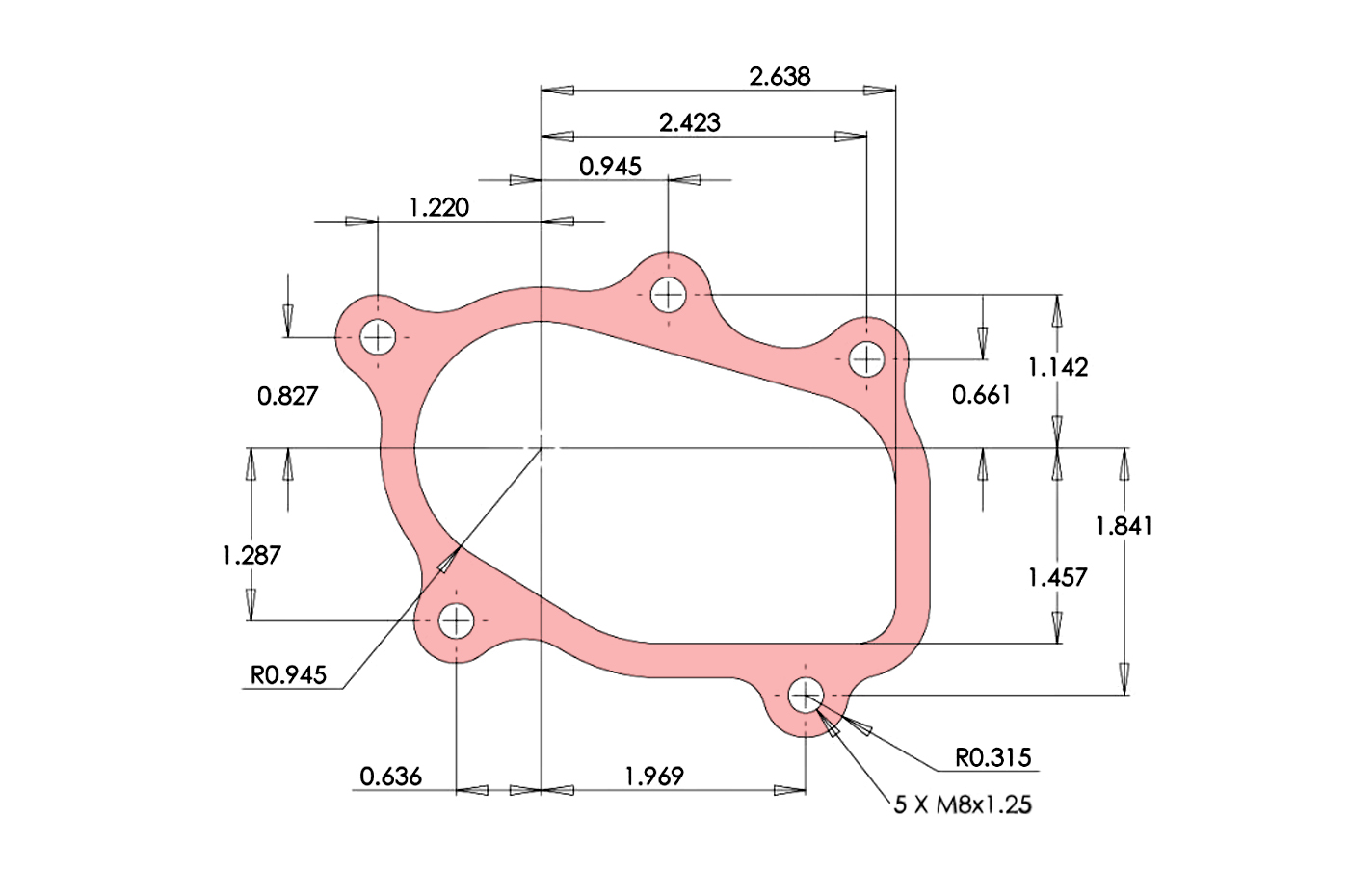
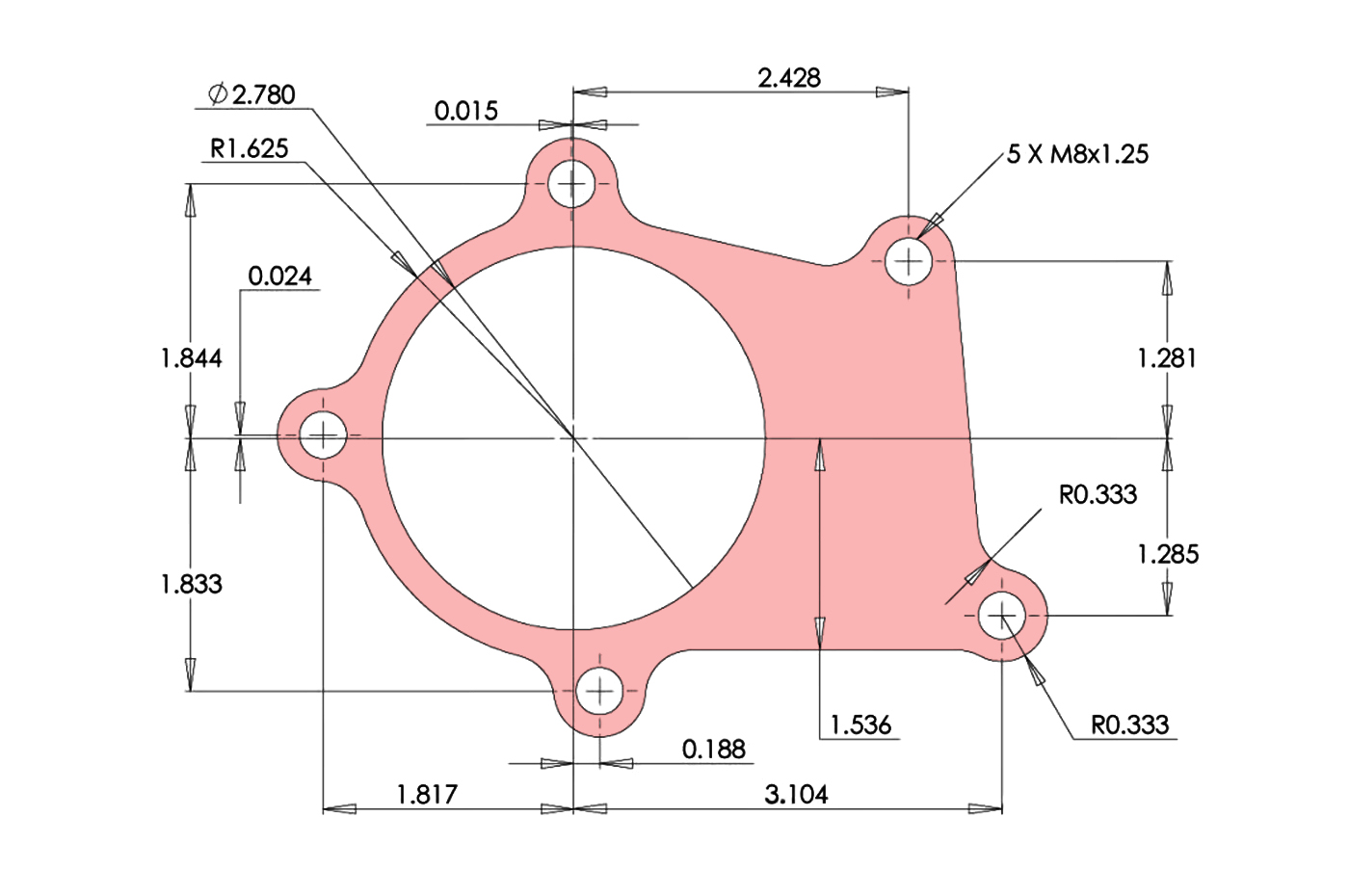
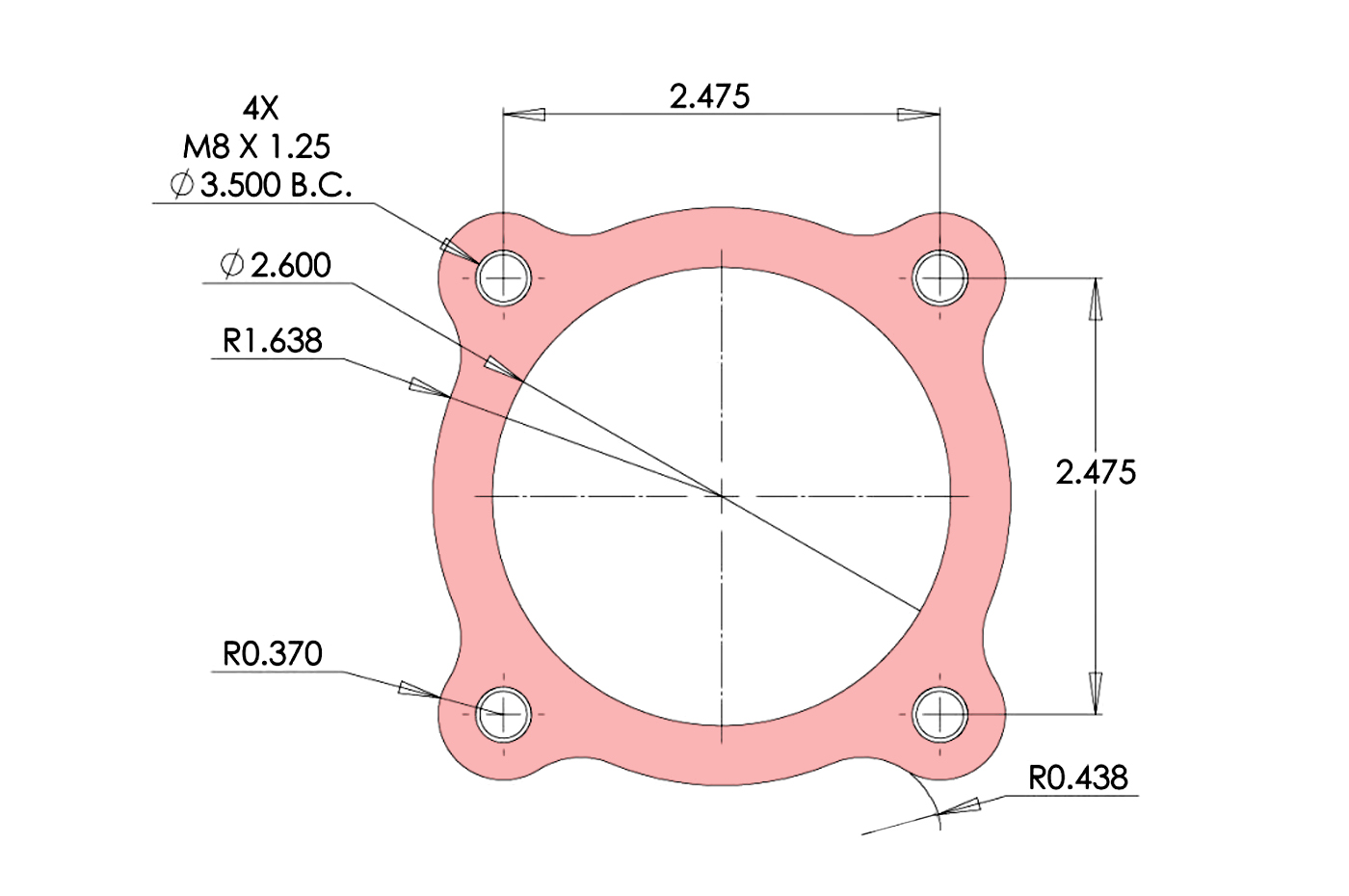
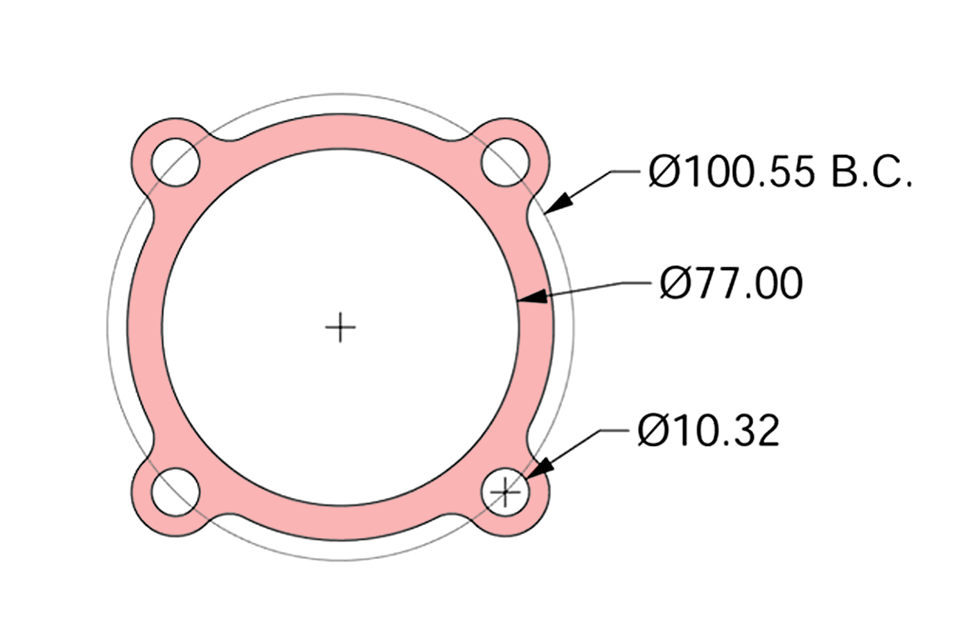
The turbine housing inlet comes in to the turbo from the exhaust manifold. Below are some of the PTE inlet flange dimensions for visual reference, as well as matching weld flanges, gaskets and v-band clamps.
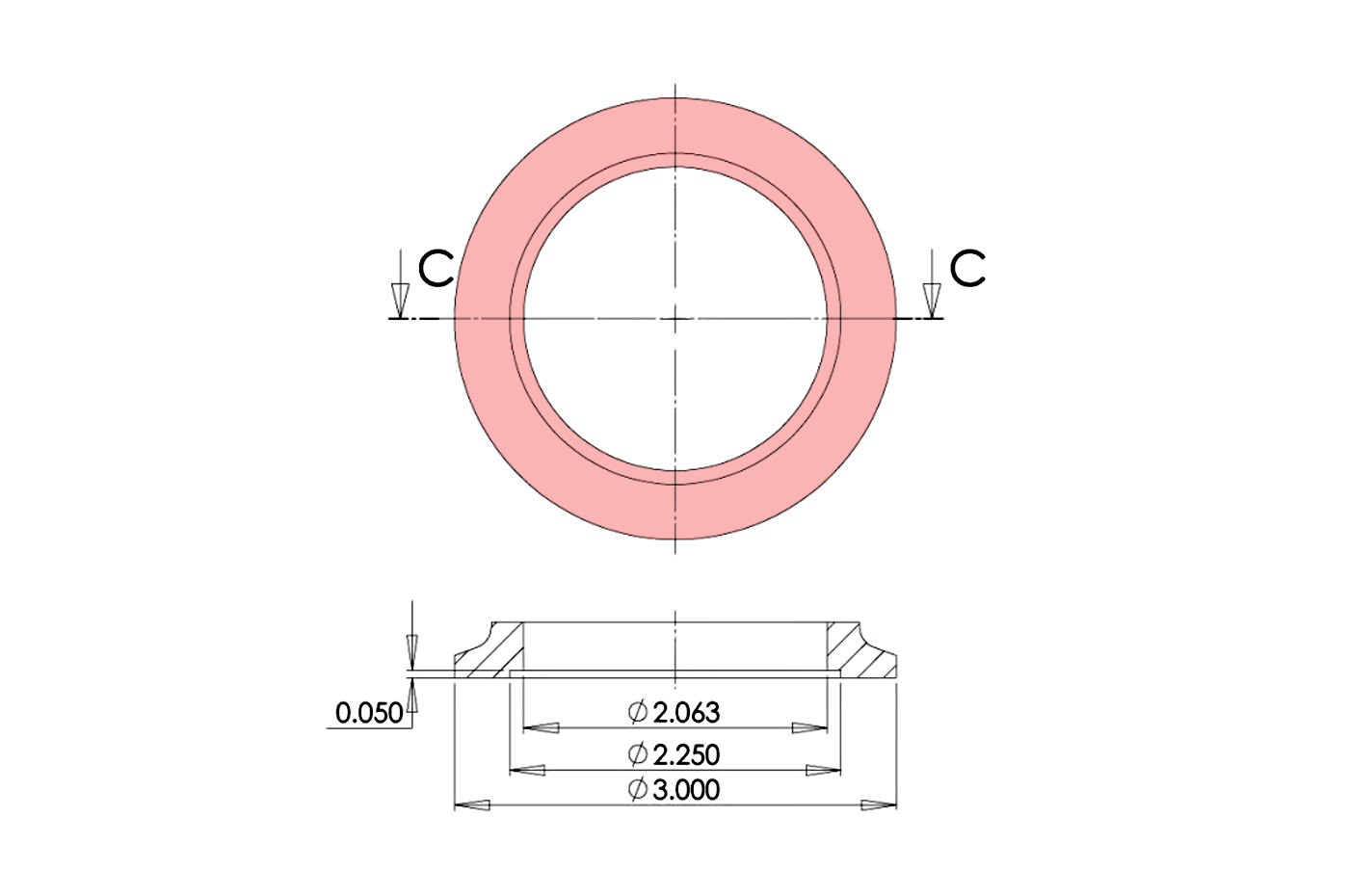
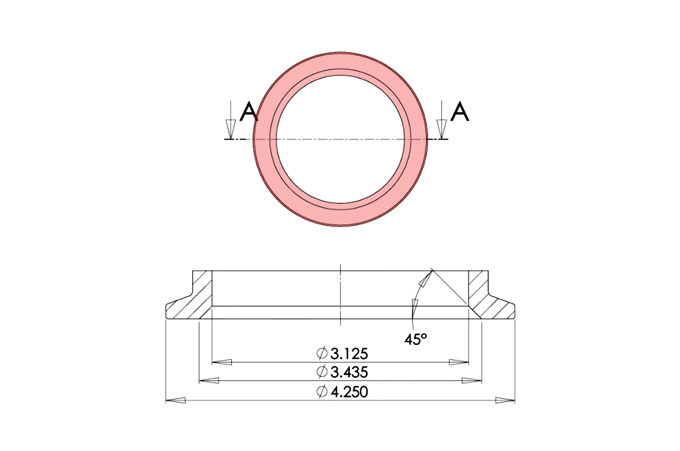
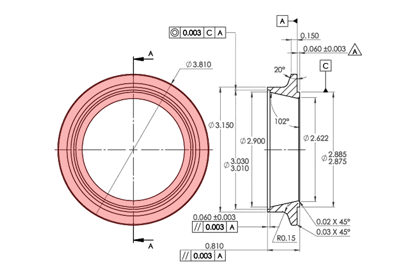
The turbine housing outlet goes out from the turbo to the exhaust/downpipe. Below are some of the PTE outlet images and dimensions for reference as well as the available matching weld flanges and v-band clamps.
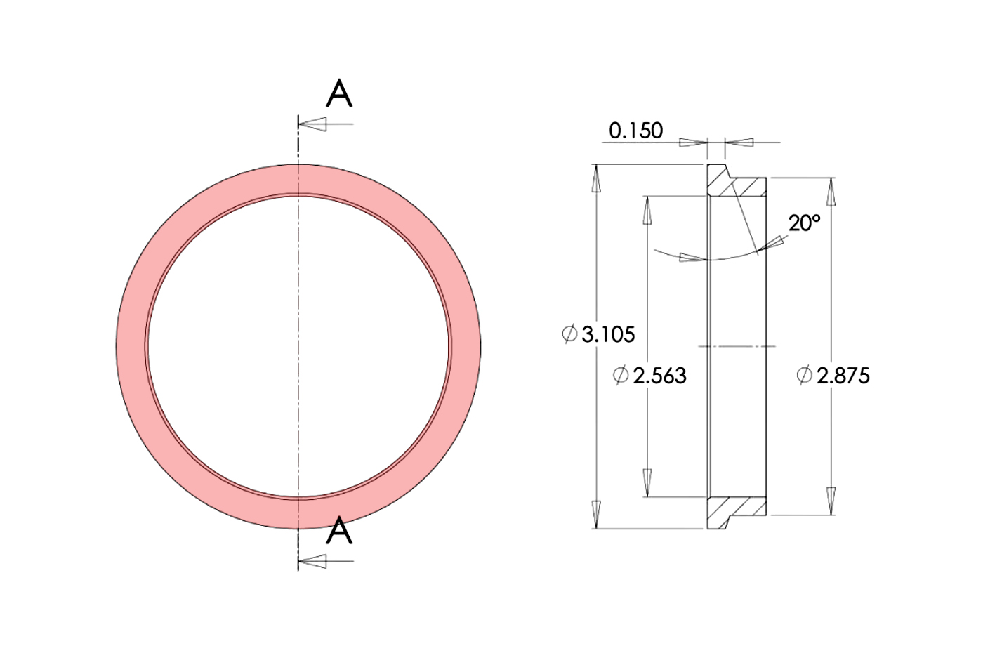
PTE T3 V-Band Outlet:
• 3.105" OD
• Housings with T3 4-Bolt Inlet
• Outlet Flange (PTP074-3012)
• Outlet Clamp (PTP071-1026)
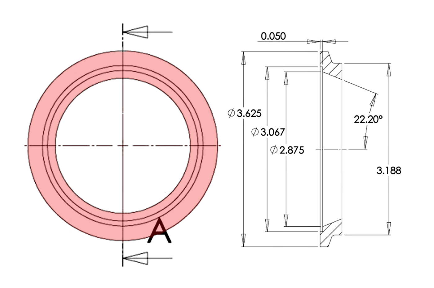
PTE T3 THV V-Band Outlet:
• 3.625" OD
• For T3 SS VB Housings (TH3V)
• Fits *some* T4 VB/VB
• Outlet Flange (PTP074-3050)
• Outlet Clamp (PTP071-1029)
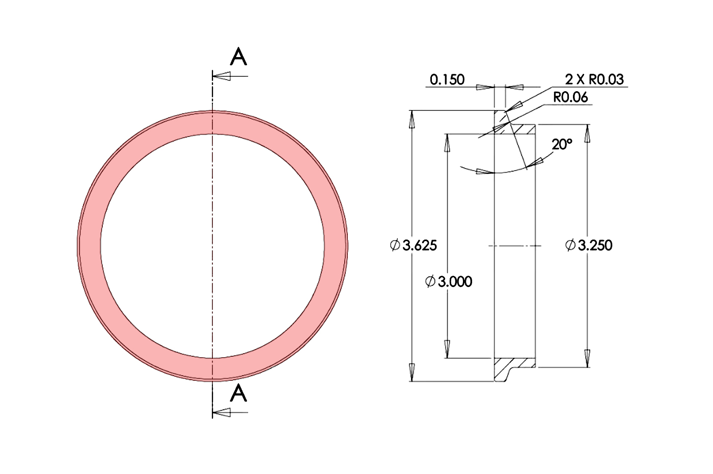
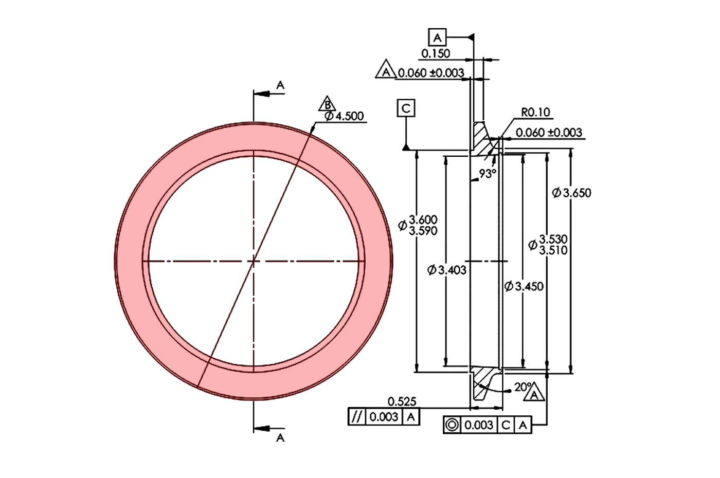
PTE T4 V-Band Outlet:
• 3.625" OD
• Housings with T4 4-Bolt Inlet
• Flange (PTP074-3014) MS to 3.0"
• Flange (PTP074-3036) SS to 3.5"
• Outlet Clamp (PTP071-1029)
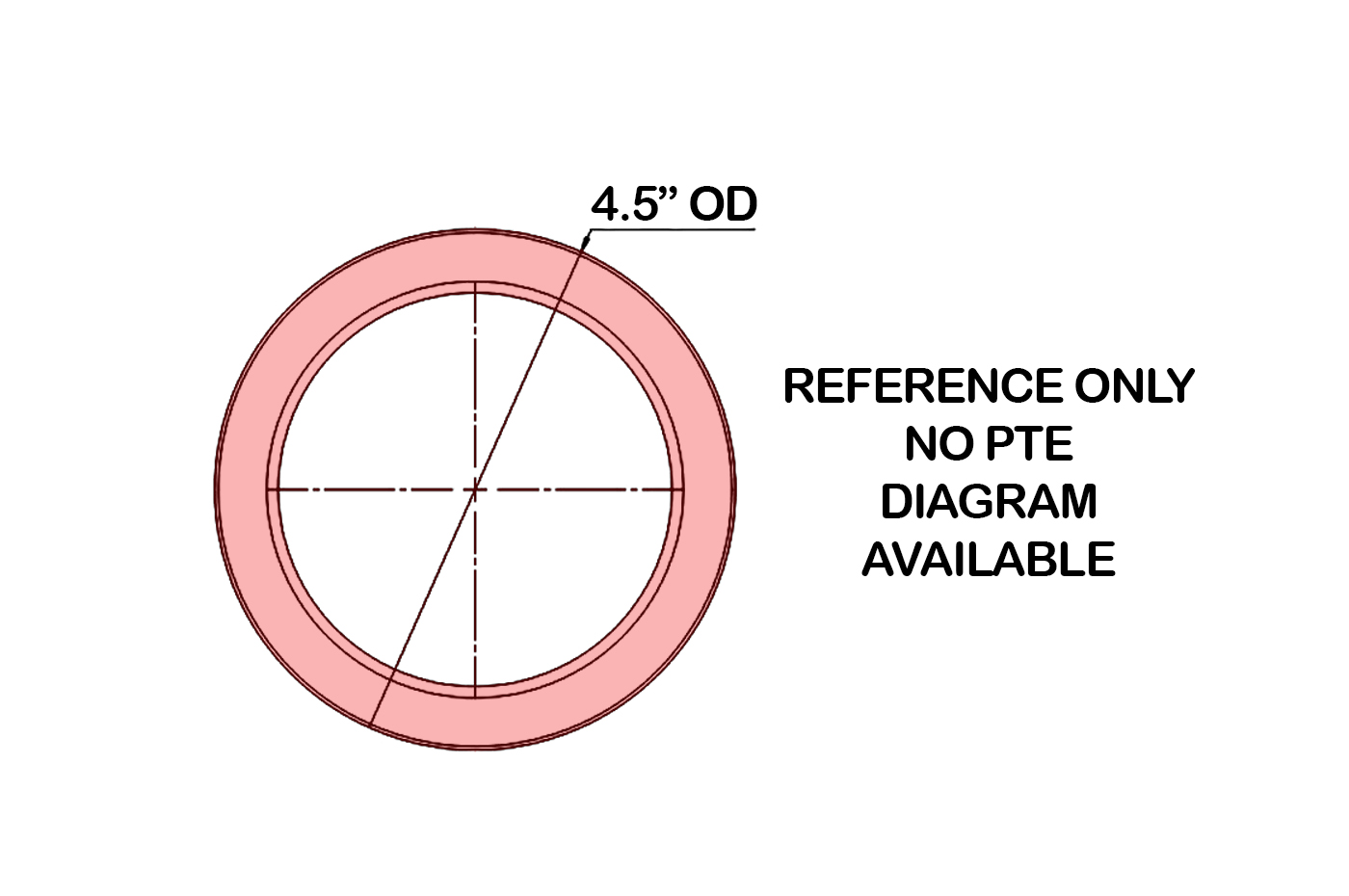
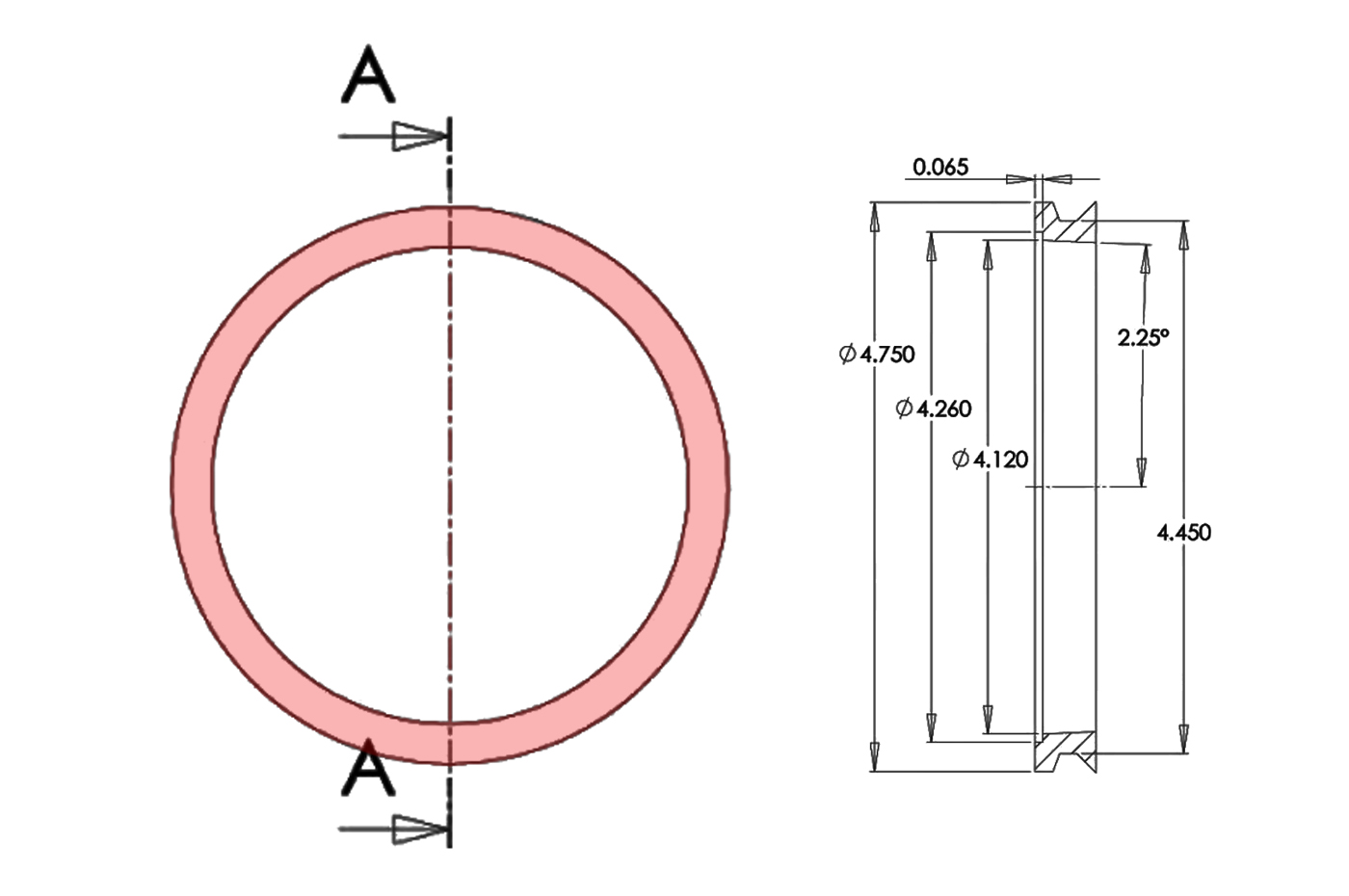
PTE T4 VB/VB SS Outlet:
• 4.5" OD
• For T4 Stainless Housings (TH4V)
• Flange (PTP074-3070) SS to 3.5"
• Flange (PTP074-3072) SS to 4.0"
• Outlet Clamp (PTP071-1032)
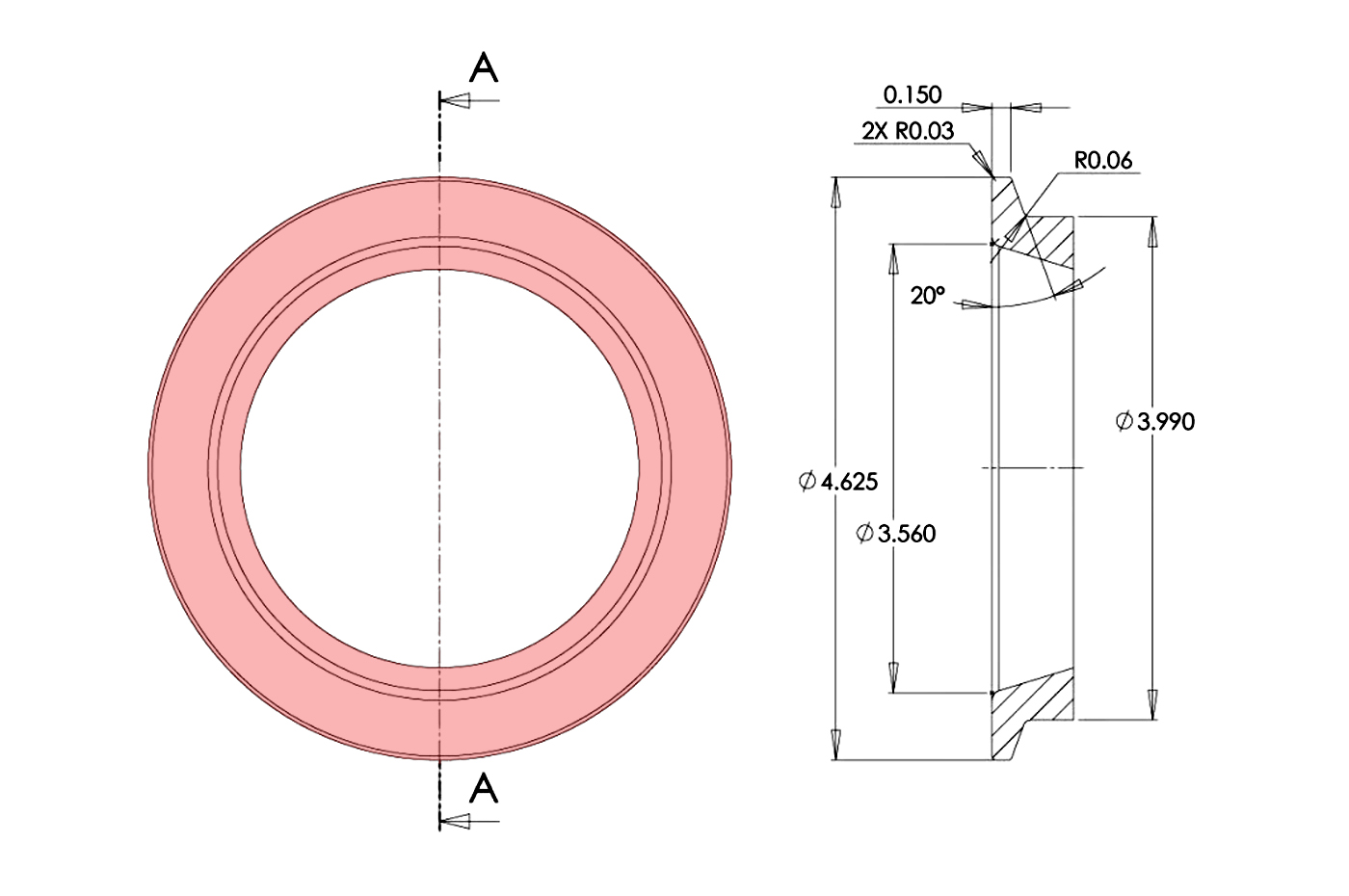
PTE T4 Sportsman Outlet:
• 4.625" OD (aka GT42)
• Housings with T4 4-Bolt Inlet
• Flange (PTP074-3045) SS to 4"
• Flange (PTP074-3047) MS to 4"
• Outlet Clamp (PTP071-1038)
PTE T4 PT88 V-Band Outlet:
• 4.5" OD (aka TH47TAN)
• Housings with T4 4-Bolt Inlet
• Flange (PTP074-3023) SS to 4"
• Outlet Clamp (PTP071-1032)
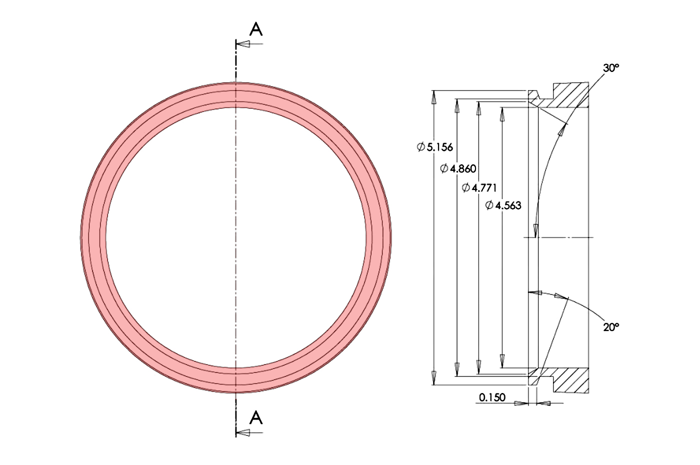
PTE T5/T6 V-Band Outlet:
• 5.156" OD
• Housings with T5/T6 Inlet
• Flange (PTP074-3030) SS to 5"
• Flange (PTP074-3029) MS to 5"
• Outlet Clamp (PTP071-1035)
PTE T3 V-Band Outlet:
• 3.105" OD
• Housings with T3 4-Bolt Inlet
• Outlet Flange (PTP074-3012)
• Outlet Clamp (PTP071-1026)
PTE T3 THV V-Band Outlet:
• 3.625" OD
• For T3 SS VB Housings (TH3V)
• Fits *some* T4 VB/VB
• Outlet Flange (PTP074-3050)
• Outlet Clamp (PTP071-1029)
PTE T4 V-Band Outlet:
• 3.625" OD
• Housings with T4 4-Bolt Inlet
• Flange (PTP074-3014) MS to 3.0"
• Flange (PTP074-3036) SS to 3.5"
• Outlet Clamp (PTP071-1029)
PTE T4 VB/VB SS Outlet:
• 4.5" OD
• For T4 Stainless Housings (TH4V)
• Flange (PTP074-3070) SS to 3.5"
• Flange (PTP074-3072) SS to 4.0"
• Outlet Clamp (PTP071-1032)
PTE T4 Sportsman Outlet:
• 4.625" OD (aka GT42)
• Housings with T4 4-Bolt Inlet
• Flange (PTP074-3045) SS to 4"
• Flange (PTP074-3047) MS to 4"
• Outlet Clamp (PTP071-1038)
PTE T4 PT88 V-Band Outlet:
• 4.5" OD (aka TH47TAN)
• Housings with T4 4-Bolt Inlet
• Flange (PTP074-3023) SS to 4"
• Outlet Clamp (PTP071-1032)
PTE T5/T6 V-Band Outlet:
• 5.156" OD
• Housings with T5/T6 Inlet
• Flange (PTP074-3030) SS to 5"
• Flange (PTP074-3029) MS to 5"
• Outlet Clamp (PTP071-1035)
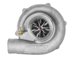
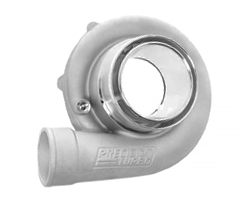
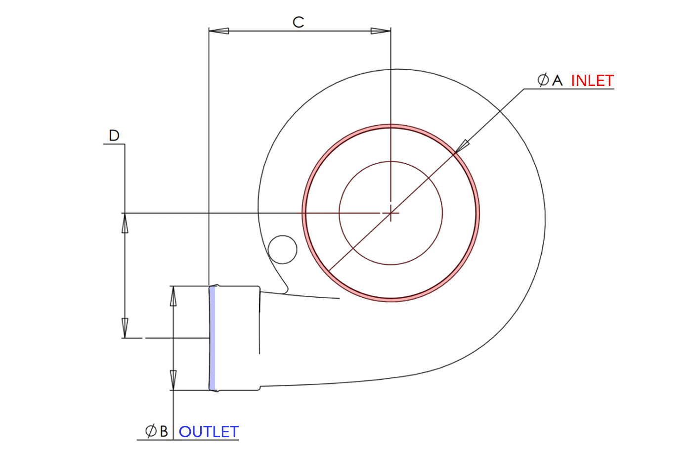
The compressor cover inlet brings in fresh air from the intake. The outlet goes out to the intercooler piping. Below are some of the PTE compressor cover dimensions and visual reference.
Most inlets and outlets will take a standard coupler, some use a v-band flange and clamp connection.
PTE's newest Jet Fighter cover gives the turbo an extra cool spooling and whistling sound enhancement without sacrificing efficiency and power.
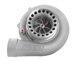
The port shroud (aka ported shroud or anti-surge) compressor covers help alleviate compressor surge.
Compressor Cover:
Reference Diagram Above
A Inlet
B Outlet
C
D
B Cover
2.8"
2.0"
4.25"
2.25"
E Cover
3.0"
2.0"
4.35"
2.25"
Jet Fighter
4.0"
2.25"
4.35"
3.0"
S/SP Cover
4.0"
2.25"
4.35"
3.0"
SPC Cover
4.0"
2.25"
4.35"
3.0"
H/HP Cover (CCH)
4.0"
3.0"
5.45"
3.10"
Sportsman (42/CC42)
4.0"
4.2" (V-Band)
4.85"
4.25"
Promod (10/CC10)
5.0"
4.2" (V-Band)
4.30"
4.95"
P Cover (CCP)
7.0"
4.0"
5.75"
5.45"
PTE Turbo FAQ | What does it all MEAN?
There are a lot of codes and abbreviations in the PTE product descriptions. Here is a quick reference to help explain what it all stands for.
Damage to a Turbocharger is generally a secondary result. Turbochargers are asked to perform in some pretty hostile environments. Any preventive measures taken at the time of installation may prevent damage. The following items should be taken into consideration for a proper turbocharger installation.
Be sure the turbocharger is receiving oil from a filtered source.
A quality paper element style oil filter is recommended.
Be sure the turbocharger has a properly sized oil feed line.
The oil return line size needs to be a minimum of a -10AN or 5/8 of an inch inside diameter or larger.
Install coolant lines if applicable.
There should be at least 1 inch of clearance around the turbocharger and any structural member of the car.
There needs to be at least one flexible rubber style compressor cover discharge tube coupling.
A ported shroud compressor cover should be utilized whenever possible.
Common Causes of Turbo Issues:
Turbochargers leaking oil and smoking. Turbochargers will leak oil and smoke due to multiple reasons which are typically installation related.
1. An inadequate oil return is the primary cause of oil leakage.
The turbocharger needs to be mounted as high as possible so the oil will gravity return to the engine.
The oil return line needs to be a minimum of a -10AN or 5/8 of an inch inside diameter.
Try to use tube type hose fittings that do not have any restrictive tight radius bends.
If utilizing an oil return pump, the pump should be mounted lower than the oil drain on the turbocharger. It may also be necessary to have an oil reservoir installed in the oil return prior to the pump. The return oil from the turbocharger may also contain air bubbles. The air bubbles may have to settle out of the oil before the pump will pump the oil.
If utilizing an oil return pump in the system and if the pump is not sized properly or if there is excessive crankcase pressure this may cause the turbocharger to leak oil.
2. Crankcase ventilation is critical as well. If the engine has positive crankcase pressure this will also pressurize the turbocharger’s oil drain. With the oil drain compromised due to pressure this could also cause the turbocharger to leak oil.
On systems utilizing a PCV valve be sure it is of a design used for boosted applications. Also be sure it is proper working order (not sticking closed).
If utilizing a breather catch can system be sure you are using a minimum of a -10AN or 5/8 of an inch inside diameter line. Also make sure the breather on the catch can has a large diameter opening that is at least 1 inch. Some push in style breathers may have a small diameter hole in them. As for clamp on style breathers these usually have a larger diameter opening.
Valve cover breathers should have a large diameter opening that is least 1 inch and one breather per valve cover. Some push in style breathers may have a small diameter hole in them as for clamp on style breathers these usually have a larger diameter opening.
3. Properly sized air inlets and air filters should be used. A restricted turbocharger air inlet due to improperly sized air inlet tubing, or an air filter that will not flow enough air may be the cause of a compressor side oil leak.
When using an air filter, it must be sized properly. If the air filter is too small, it will not allow the turbocharger to pull air in freely. When this happens, the filter becomes a restriction. A dirty air filter may restrict air flow as well.
When the air inlet to the turbocharger becomes restricted it may pull oil past the compressor side seal causing an oil leak.
Turbo Lubrication:
All turbochargers rely on clean filtered lubrication with sufficient volume and pressure. Probably the number one cause of turbocharger failure is due to dirty or contaminated lubrication.
It is strongly recommended that a quality paper element type filter is used. Stainless steel mesh screen type filters typically do not have the filtering capacity of a quality paper element type filter. Some examples of the stainless steel mesh screen type filters are System 1, Oberg, and the Moroso Omni-Filter.
A remote mounted oil filter housing with a dedicated turbocharger lubricant feed line would be best.
Caution must be taken if an inline type of lubricant filters are used. When using an inline filter it must be serviced at regular intervals. Inline filters can plug up and starve the turbocharger of lubricant if not serviced at regular intervals.
Turbo Lubrication | Feed Location:
Turbocharger lubrication feed locations may vary from engine manufacture and application. Sometimes the best resource for information on turbocharger lubricant feed locations is from the professionals that specialize in a particular vehicle or engine.
A recommended location to pick up lubricant to feed the turbocharger would be a pressure location as close to the outlet side of the oil filter.
A remotely mounted oil filter header is best location to feed a turbocharger with filtered lubricant. Be sure to feed the turbocharger from the filtered side.
It is not recommended to use an oil filter sandwich plate as a source to pick up lubricant to feed a turbocharger. We have seen cases where these do not filter the lubricant properly and the turbochargers fail due to contaminated.
Turbo Lubrication | Feed Lines:
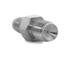
It is not recommended that any journal bearing turbocharger utilizes an oil feed line restrictor. If a turbocharger is leaking oil or smoking this is typically caused by another issue. If we have gone over a customer’s installation in detail and the turbocharger continues to leak oil and smoke, then and only then would we suggest an oil feed line restrictor. We would start with a restrictor of .090 inch and work down to a restrictor no smaller than .065 of an inch. This will be done on a case-by-case basis only.
Journal Bearing Turbo Oil Feed Line Sizes:
All small single journal bearing turbocharger applications utilizing turbocharger sizes up to HP42 should utilize -4AN or 1/4 inch inside diameter oil feed line.
All single journal bearing turbocharger applications utilizing turbocharger sizes HP47 and up should utilize -6AN or 3/8 inch inside diameter oil feed line.
All small twin journal bearing turbocharger applications utilizing turbocharger sizes up to HP42 should utilize a -6AN or 3/8 inch inside diameter main oil feed line into a Y block to -4AN or 1/4 inch inside diameter turbocharger oil feed lines. The -4AN turbocharger oil feed lines from the Y block to the turbochargers should be equal in length.
All twin journal bearing turbocharger applications utilizing turbocharger sizes HP47 and up should utilize -8AN or 1/2 inch inside diameter main oil feed line into a Y block to -6AN or 3/8 inch inside diameter turbocharger oil
feed lines. The -6AN turbocharger oil feed lines from the Y block to the turbochargers should be equal in length.
Ball Bearing Turbo Oil Feed Line Sizes:
The oil feed to ball bearing turbochargers may be restricted but may not always be necessary. If a ball bearing turbocharger is supplied with an oil feed restrictor fitting it is suggested that this fitting be utilized.
All single ball bearing turbocharger applications should utilize -4AN or 1/4 inch inside diameter oil feed line.
All twin ball bearing turbocharger applications should utilize a -6AN or 3/8 inch inside diameter main oil feed line into a Y block to -4AN or 1/4 inch inside diameter turbocharger oil feed lines. The -4AN turbocharger oil feed lines from the Y block to the turbochargers should be equal in length.
Turbo Lubrication | Return Lines:
The oil return is probably the most overlooked item in a turbocharger installation. It is the primary reason why a turbocharger will leak oil and smoke. The oil return is crucial to a proper turbocharger installation.
It is best that the turbocharger is mounted as high as possible so the oil will gravity returns to the engine. If returning the oil back to the oil pan the oil return line fitting must be installed above the oil level in the oil pan.
The minimum recommended oil return line size is -10AN or 5/8 inch inside diameter. The fittings utilized should be of a free-flowing design. It is also advised sharp turns and tight radius fittings be kept to a minimum.
On installations where the turbocharger is mounted low, and an oil return pump is utilized it is best if the pump is mount lower than the oil drain on the turbocharger so that the oil drain will gravity feed the pump. Turbocharger oil return pump system can become very complex and must be designed properly to function. The proper size lines, reservoir, time delay relay, electric or mechanical pumps are crucial to a properly functioning oil return system.
Turbo Coolant Lines:
If a turbocharger has locations on the bearing housing for coolant lines coolant must be run through the turbocharger. If coolant is not run through the turbocharger, it will fail due to excessive heat.
Turbo Clearance:
Proper clearance around the turbocharger and any structural member of the vehicle is crucial to the turbocharger’s longevity. Anytime a structural member of the vehicle comes in contact with the turbo it can cause side loading. Side loading is when stresses are placed on the outside of the turbocharger which may push, pull, or twist the turbocharger which may cause the rotating group to crash into the housings.
At least 1 inch of clearance should be maintained between the turbo and any structural member of the vehicle to prevent side loading. This becomes even more critical on high horsepower applications where chassis flex is more prevalent. This also includes any body panels which may flex from the forces applied at higher MPH.
At least one flexible rubber style compressor discharge tube coupling should be utilized. Compressor discharge tubes can act like a lever which can pull or twist the compressor cover and cause side loading.
If it is necessary to support the weight of the turbocharger it is best to do so by supporting it from the turbine housing inlet flange or the center housing. Mounting locations on the Precision Turbo large V-band (pro mod) style turbine
housings may also be utilized to support the weight of the turbocharger.